
Introduction#
I’ve always been curious about hardware hacking. However, I’ve never actually done it before. Though, it seemed rather easy at first glance; connect to the right pins and talk over the right protocol, and you’re in!
So, I decided to buy a Tigard along with a BitMagic Basic logic analyzer. This was back in June of 2025. The package arrived, and they simply sat in my bag doing nothing for an entire year.
Present Day#
I came across an electronic shelf label by Vusion, formerly SES-imagotag1.
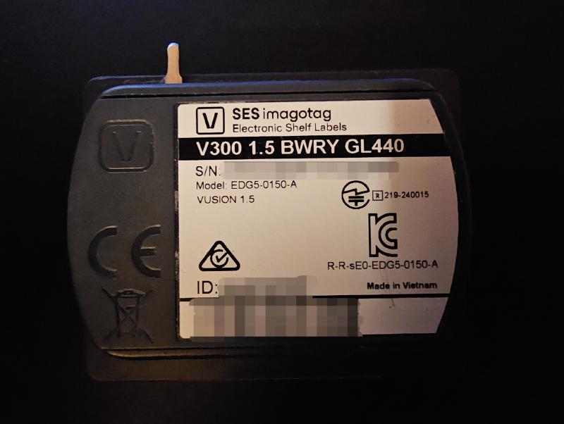
It’s labeled as a “V300 1.5 BWRY GL440”. I had no idea what any of that meant, but by digging through the manufacturer’s products website, V300 is the model, BWRY are the colors it supports (black, white, red, yellow), 1.5 is the size, I’m guessing. I don’t know what the GL440 stands for.
There is another model number on the back, and that reads EDG5-0150-A. Plugging that into a search engine, we get the FCC filings. Unfortunately, the User Manual PDF is gone, and I didn’t bother looking for it, maybe it’s still mirrored somewhere.
All I got out of it is that the thing supports 2.4 GHz communication, which may or may not come in handy later.
Oh yeah, and the front has an IR sensor, and an LED light for blinking the label when an employee uses that feature on their store phones.
It also does NFC. I tapped my phone to it, all it did was give me a link to a NFC subdomain of the manufacturer website with the tag’s ID filled in. The link itself is 403. I’m guessing this is for internal use at the store so employees can tap on the shelf and get the ID instead of scanning the barcode on the bottom or backside.
I also checked for any Bluetooth LE, but no dice. This thing is probably communicating over a proprietary 2.4 GHz protocol, and more than likely it’s passive and is just waking up every now and then to listen to any signals, hence the long advertised battery life.
Disassembly#
Taking the back cover off, I was greeted by a SES-imagotag-branded CR 2450 3V lithium battery.
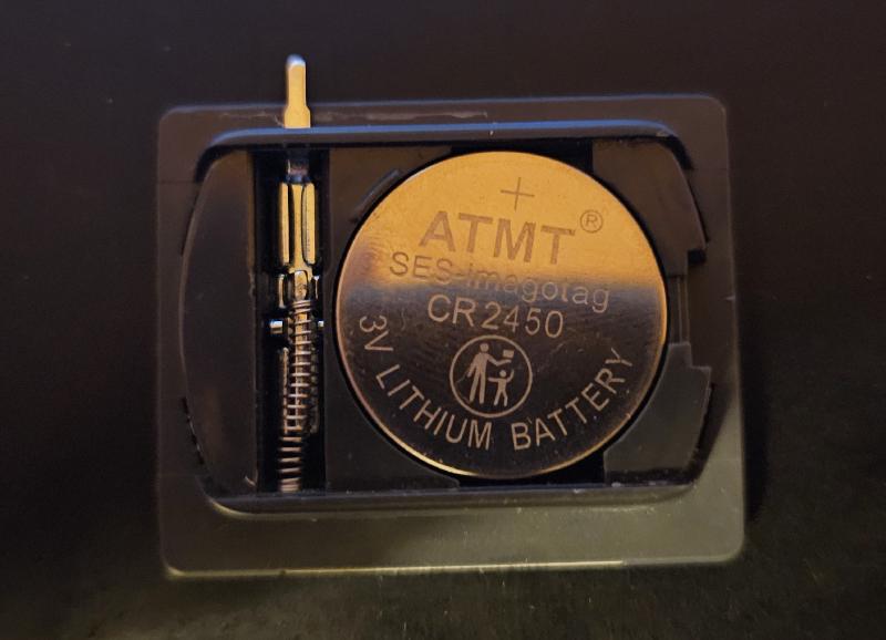
I used a guitar pick to pry open the front. I worried that I would crack the delicate display, but the disassembly was rather easy and straightforward.
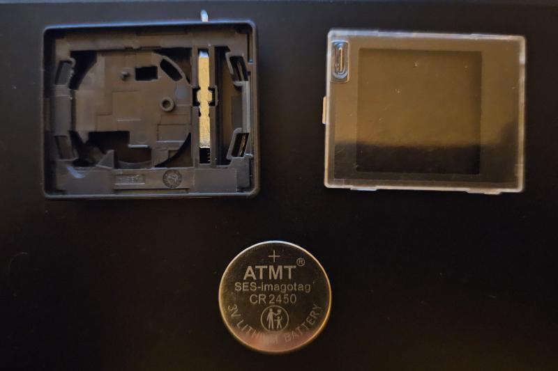
Why no board pictures?
You may be wondering why I haven’t showed the display and the board. That’s shrimply because I’m taking these pictures after I had already soldered a bunch of wires to the board, so it doesn’t make sense to show it in that state at this point. I’ll show you the board in the next section, I promise.
The Board#
That was my first thought.
The board itself is small. The components are tiny.
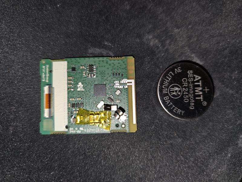
It was very difficult to photograph this board with my smartphone. I later learned to use the wide-angle x0.6 lens, but that still blurred the edges.
The display was stuck to the board with double-sided tape. It took me a good while to get it unstuck without snapping the display in half. I used the same guitar pick to basically dig through the double-sided tape until the whole thing came loose.
I used my laptop screen with a white image at max brightness, and the x0.6 wide-angle camera on my Samsung Galaxy S23 Ultra in Pro mode to take these photos. I later used the raw image files for tracing some of the pins.
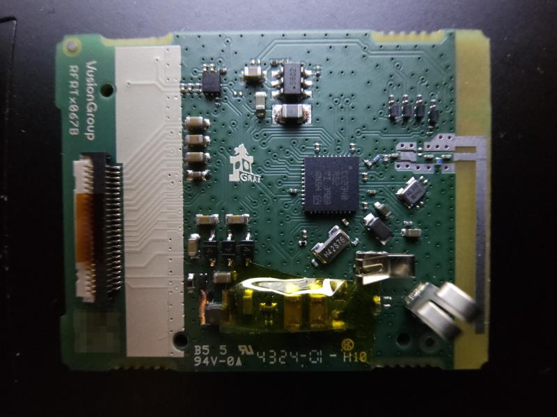
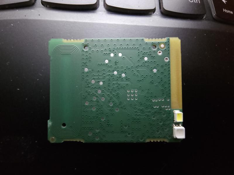
The MCU#
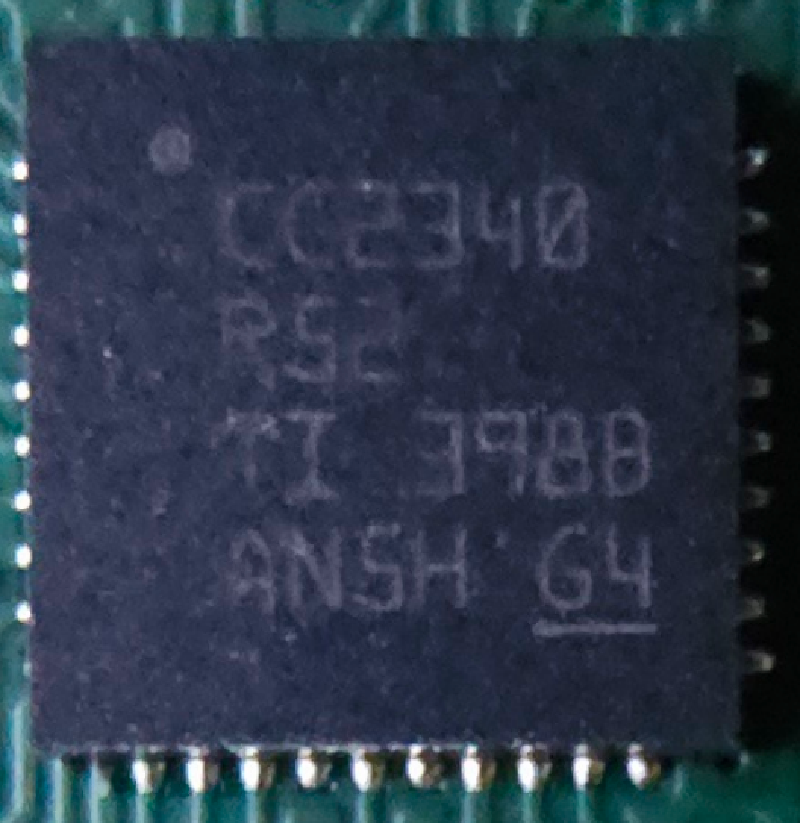
The chip is a Texas Instruments CC2340R5 from the SimpleLink™ Family of 2.4 GHz Wireless MCUs. Makes sense. I downloaded the datasheet and began perusing.
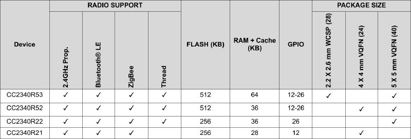
The datasheet2 was very helpful in figuring out what each pin does.
Unfortunately, as this is my first time doing anything like this, I am still a noob. A lot of the information in this document probably flew over my head and I most likely missed a lot of important details. However, I was able to learn that the chip has SWD support on pins 11 (SWDIO) and 12 (SWCLK). I would also learn that these pins can be muxed (which, from my understanding, means the pins’ functions can be changed depending on the mux mode).
Hardware Hacking?#
I know next to nothing about hardware hacking. This should be abundantly clear by now. I’m just emulating what I had seen others do, be it on YouTube or other blog posts.
Tracing#
Itching to actually connect to this thing, I decided to figure out which pads on the back go to the SWD pins.
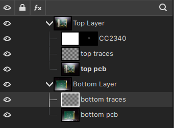
I loaded up the raw image files from my phone into GIMP, and began by flipping the image of the bottom of the board vertically. I then overlaid it on top of the other image, reduced the opacity a bit, then used the handle transform tool in order to line up the vias on the board.
I then made two layer groups, one for the top side, one for the bottom. Each has the image and a transparent layer that would represent the traces I would draw with the brush tool in different colors.
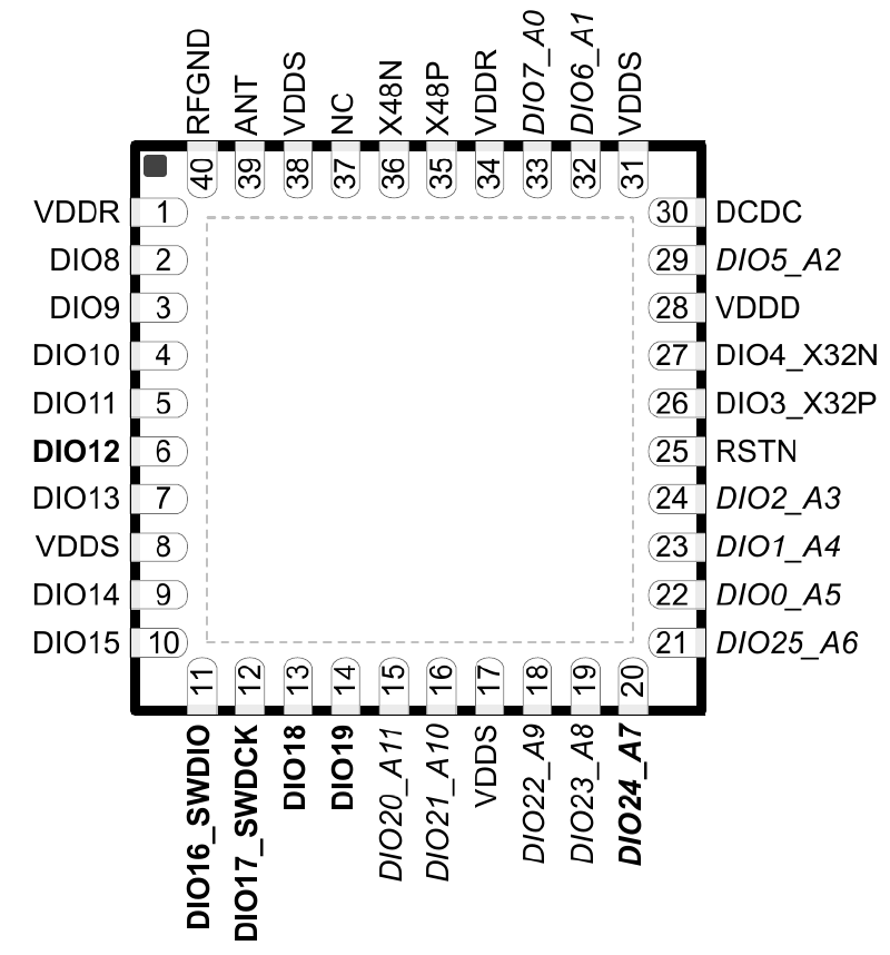
I also decided to overlay this nice diagram of the MCU itself in order to make it easier to know which pin is which. I used the image itself as a mask, this let me overlay it nicely.
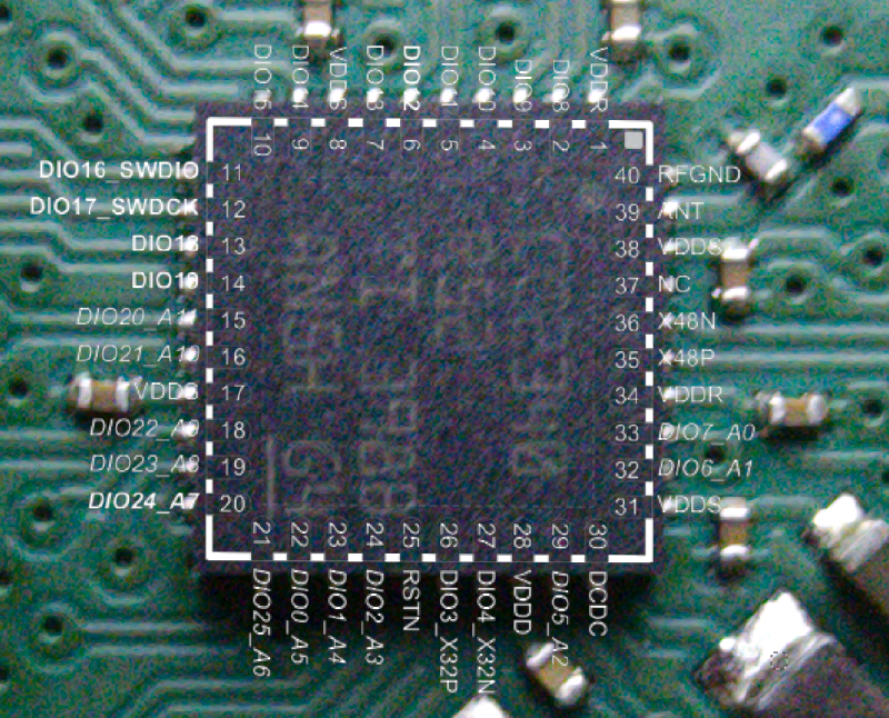
I then traced the SWDIO in red, and SWCLK in blue. I later also traced RSTN in green.
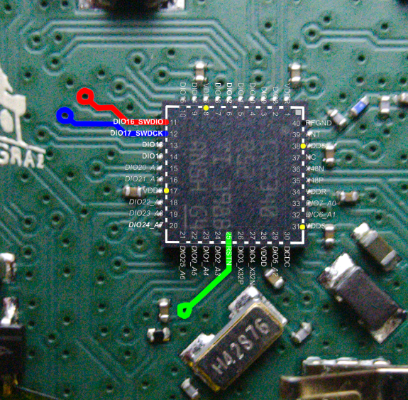
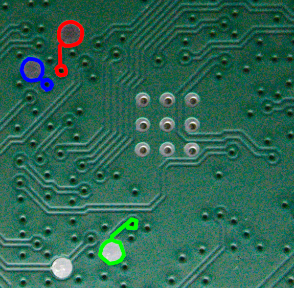
This was rather easy, I did have to take another picture through a magnifying glass to get the RSTN pin traced.
The bottom picture can be flipped again to get it in the proper orientation, and with that, I was ready to solder.
Soldering#
I had only soldered once or twice before, so I’m also inexperienced in this department. However, I watched a couple of YouTube videos on how to solder… a year ago.
Oh well, what’s better than just trying things? I remembered this time that there’s no such thing as too much flux, so I used quite a bit of it. I ended up tinning all the pads just in case.
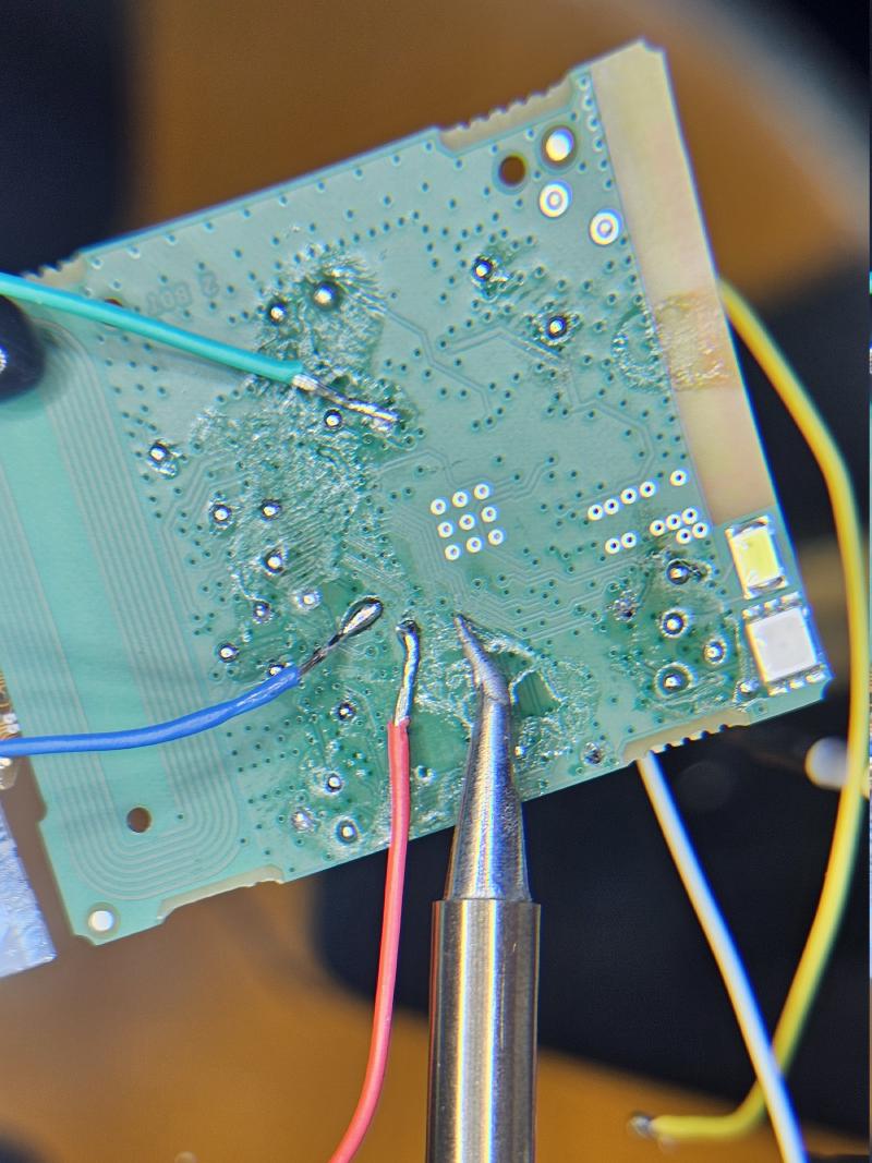
I soldered a red wire to SWDIO, a blue wire to SWCLK, and a green wire to RSTN, just like my traces. I also soldered a white wire to the ground terminal and a yellow wire to the positive terminal in order to power the board via the Tigard.
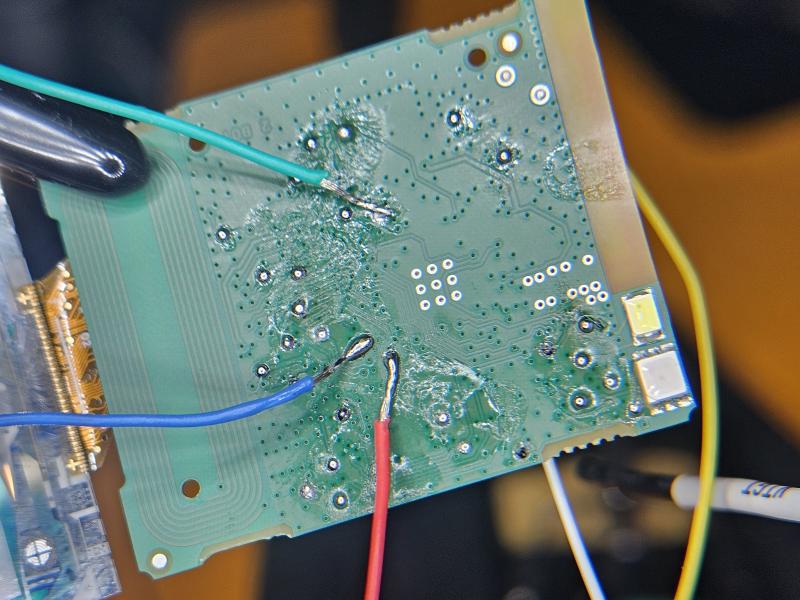
I used a PINECIL V2 with some soldering tips I got off Amazon. I’m sorry, I don’t remember which ones, it’s been a while, but the tip was thin enough to let me work easily.
The Jig#
The Software: Part 1#
In order to talk to the MCU via the Tigard, I needed the right software on my machine. After a bit of digging, OpenOCD seemed to be THE open source tool to use to talk to MCUs.
Despite what the Tigard GitHub page says, SWD does work on the JTAG header as well. When you flip the switch to SWD mode, the SWD pins are connected in parallel on the Cortex header and the JTAG header. This was not very clear, so I had to ask on the 1BitSquared Discord.
Installing OpenOCD was as simple as running:
$ sudo USE="ftdi" emerge -1 dev-embedded/openocd
Yes, I’m using Gentoo. The ftdi USE flag is required, because the Tigard is FTDI-based. The same GitHub page also gives us a convenient Tigard config for OpenOCD:
adapter driver ftdi
transport select swd
ftdi vid_pid 0x0403 0x6010
ftdi channel 1
adapter speed 2000
ftdi layout_init 0x0028 0x002b
ftdi layout_signal SWD_EN -data 0
ftdi layout_signal nSRST -data 0x0020
The Hacking: Part 1#
I couldn’t wait to test this. This was before I had the RSTN pin mapped and connected, I simply plugged my Tigard into my machine: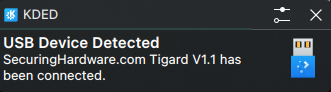
I then ran OpenOCD:
$ openocd -f ./tigard-swd.cfg
Open On-Chip Debugger 0.12.0
Licensed under GNU GPL v2
For bug reports, read
        http://openocd.org/doc/doxygen/bugs.html
Info : FTDI SWD mode enabled
Info : Listening on port 6666 for tcl connections
Info : Listening on port 4444 for telnet connections
Info : clock speed 2000 kHz
Warn : gdb services need one or more targets defined
So yeah. I don’t really know how to use OpenOCD. I just plugged stuff in and ran the commands given. OpenOCD is running. It is connected to the Tigard, but nothing else is happening. I later learned, that I also need a config for the specific MCU I’m targeting, I also learned that the upstream OpenOCD does not come with the config for the MCU I’m trying to talk to.
Failure: Part 1#
At this point, I was kind of lost. I didn’t know how to proceed.
I asked some people on Discord, but didn’t really get anywhere. My one friend put all the info I ranted to him into ChatGPT and it spat out a bunch of slop that I really didn’t want to read. Though, it did encourage me to try again later on.
I did try other things. I tried to connect to different UART ports hoping to get something out of it, but I got nothing.
I also tried to probe every single pad on the back with the logic analyzer. I got nothing promising out of it, so I shelved the project for a couple of weeks.
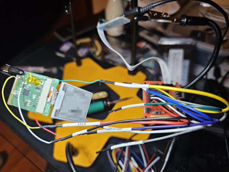
I didn’t mention this, but my first “jig” wasn’t even a jig. The whole setup was the board lying on my table along with the Tigard. I held the board in my hand along with the battery to power it. It was very crude and janky, and to be honest, I did it because I didn’t want to put the effort into wiring up everything properly.
I did eventually solder more wires as you’ve seen, so I learned my lesson here.
Hardware Hacking.#
The Software: Part 2#
Logic Analyzer#
I didn’t talk about the logic analyzer. Let’s talk about the logic analyzer. It is a BitMagic Basic. I did play around with it when I first bought it, I set up all the tools for it a long time ago, so I still kind of knew what I had to install to get it working. Its GitHub page says:
BitMagic-Basic is a simple USB High Speed Logic Analyzer compatible with Sigrok and is based on the fx2grok-flat design.
But what does this mean? Well, Sigrok is a portable, cross-platform, Free/Libre/Open-Source signal analysis software suite3.
fx2grok simply means it’s an FX2-based device. That gives us the clue on how to set this up.
Running emerge -s sigrok I get a couple of interesting results:
$ emerge -s sigrok
*  sci-electronics/sigrok-cli
      Latest version available: 0.7.2-r1
      Latest version installed: [ Not Installed ]
      Size of files: 225 KiB
      Homepage:      https://sigrok.org/wiki/Sigrok-cli
      Description:   Command-line client for the sigrok logic analyzer software
      License:       GPL-3
...
*  sys-firmware/sigrok-firmware-fx2lafw
      Latest version available: 0.1.7-r2
      Latest version installed: [ Not Installed ]
      Size of files: 146 KiB
      Homepage:      https://sigrok.org/wiki/Fx2lafw
      Description:   Firmware for Cypress FX2 chips for use as simple logic analyzer hardware
      License:       GPL-2+
Yes, I probably want the CLI tool, and I definitely want the fx2lafw firmware. However, I would really like a GUI. Luckily, the Sigrok wiki mentions PulseView, which is also available in the Gentoo repos.
I installed everything with:
$ sudo emerge -1 sci-electronics/pulseview sys-firmware/sigrok-firmware-fx2lafw
Now, when I plug the BitMagic Basic into my machine, it shows up in PulseView.
TI’s OpenOCD#
Having researched how OpenOCD actually works, I needed the appropriate target config in order to talk to the MCU. Luckily, Texas Instruments has their own fork of OpenOCD. I quickly wrote up an ebuild for it, so I can install it:
Quick plug to the repo with random stuff that I made ebuilds for, maybe you’ll need it, I don’t know.
I then installed ti-openocd, and now I had the ti_cc23xx.cfg target to use.
The Hacking: Part 2#
I plugged the Tigard in, it sent power to the board. I made sure the switch was set to SWD mode, and the voltage switch was set to 3.3V. I ran the command:
$ ti-openocd -f ./tigard-swd.cfg -f /usr/share/ti-openocd/openocd/scripts/target/ti_cc23xx.cfg
Open On-Chip Debugger 0.12.0+dev-snapshot (2026-07-30-20:50)
Licensed under GNU GPL v2
For bug reports, read
        http://openocd.org/doc/doxygen/bugs.html
Info : FTDI SWD mode enabled
ocd_process_reset_inner
Info : Listening on port 6666 for tcl connections
Info : Listening on port 4444 for telnet connections
Info : clock speed 2000 kHz
Error: Error connecting DP: cannot read IDR
An error. It cannot read the IDR. Hmm. I tried looking up how to fix this. I must admit, I even used a LLM to help me with this, but I got nowhere.
I did change the adapter speed to 10 kHz. I did also try various reset_config options, but I had no clue what I was actually doing.
$ ti-openocd -f ./tigard-swd.cfg -f /usr/share/ti-openocd/openocd/scripts/target/ti_cc23xx.cfg -d2 -c "reset_config srst_only srst_open_drain connect_assert_srst"
Open On-Chip Debugger 0.12.0+dev-snapshot (2026-07-30-20:50)
Licensed under GNU GPL v2
For bug reports, read
        http://openocd.org/doc/doxygen/bugs.html
debug_level: 2
Info : FTDI SWD mode enabled
ocd_process_reset_inner
srst_only combined srst_nogate srst_open_drain connect_assert_srst
Info : Listening on port 6666 for tcl connections
Info : Listening on port 4444 for telnet connections
Info : clock speed 10 kHz
Error: Error connecting DP: cannot read IDR

I did get a couple of “successful writes”, but I’m starting to think those were just noise.
Conclusion (aka Failure: Part 2)#
Yeah. That’s it, I suppose. I didn’t get very far.
My running theory is that SWD is disabled on the MCU by Vusion to stop this precise attack of trying to extract the firmware. Or perhaps it’s the muxing affecting the SWD pins. But, that would’ve been solved by pulling down the RSTN pin during boot I think, which I tried.
I will note down a few things that I’ve noticed and tried:
- SWDIO is low on boot by default.
- SWDIO is high with RSTN pulled down.
- Tried different adapter speeds in Tigard configuration, no dice.
- I don’t really know if the device is broken or not, it seems to be in perfect physical condition.
- Yes, I checked my connections. I even tried swapping some of them.
Most likely, I’m just inexperienced and doing something wrong. I set up a way for people to reply to blogs via email in case someone is reading this and screaming at their monitor that I’m doing it wrong.
Anyway, thank you for reading. This is my very first blog post, and it is rough around the edges. I don’t really know how to write blog posts either, so I’m just doing it to learn while documenting random stuff that I do.
Reply by Email